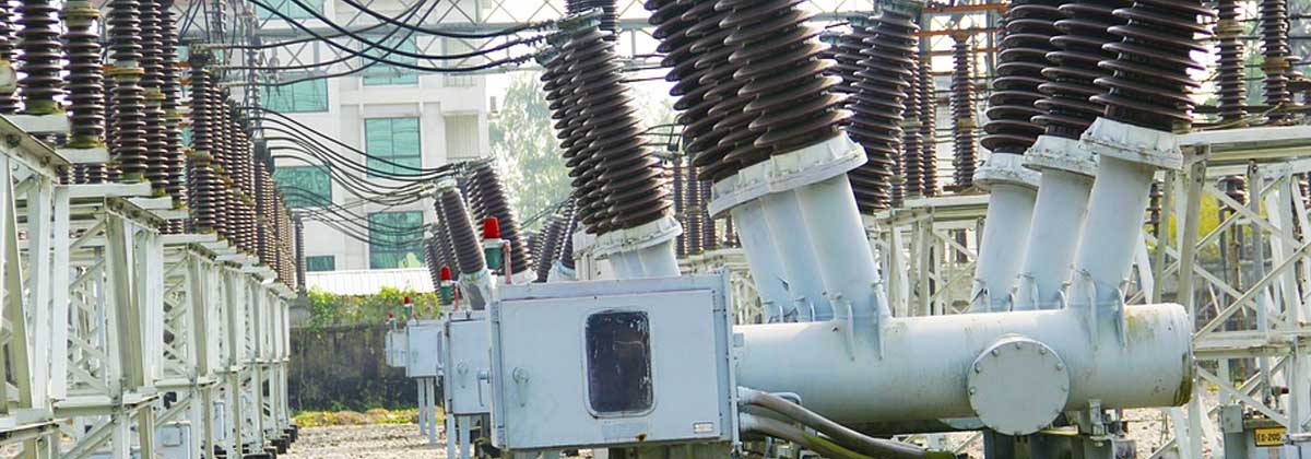
Most Common Types of Power Transformers
The transformer manufacturing process is a complex one

The transformer manufacturing process is a complex one
It involves many stages and many components. Also, there are various types of transformers ranging from Three phase transformers, chassis mounted transformers to auto-transformers and step-down transformers, depending upon the requirement. Here is a look at the transformer manufacturing process.
The most common types of power transformers include GSU (Generator Set-up), Auto-Transformers and Step-down Transformers. Each of these types has variations depending upon power capacity.
The transformer manufacturing process is a step-by-step process that involves important stages. They are
Core dimensions for the transformer are determined. Core stacking takes place which is then followed by core cutting process. The uncut slit rolls of steel or pre-cut rolls of steel are stacked and cut according to the core design.
The core is fully metered and step lapped in corner joints to improve flux distribution and to minimize loss and sound levels. The circular core shape is meant to provide windings with optimum radial support.
Core stacking follows with the help of temporary bolt guides. Single and three phase units require 2,3,4 and 5 leg cores. Oil ducts are used to control rise in temperature. Temporary, permanent or combination of banding is introduced at this stage.
The coil winding room is usually a separate area located away from other manufacturing areas. Positive pressure is used to work the horizontal or vertical winding mandrels. The conductor used is either copper magnetic wire or continuously transposed conductor. Circular concentric windings are usually preferred for most transformers. The winding type is chosen according to voltage and application. The most common types are helical, interleaved disc, continuous disc and others.
The insulation area is also separate from the other manufacturing areas for chassis mounted transformers as well as other transformers. The winding insulation cylinders and spacers are made from high density pressboard. Coil sizing force is first applied to check and adjust the winding height. Complete winding insulation packages are introduced at this stage.
Coil assembly starts by taking into account the winding type, conductor type and the insulation components.
The exposed edges of the core are bonded together with low viscosity, high strength epoxy resin. This adhesive penetrates and bonds the laminations. Prefabricated oil is placed on the bottom clamps to clamp insulation into place.
The coils are lowered over the core. The top coil clamps the insulation after which the top clamps are fixed into place. The top core is then inserted to form the final base structure.
The lead braising process takes place. The windings are clamped with external or internal tie rods. This provides them with additional support for axial forces. The leads and busbars are given additional support so they can withstand forces that arise from shipping and short circuits. The assembly is then moved on air cushions.
Lead connections are then completed and the assembly goes on to the next stage involving the vapour phase unit. Here the entire core and coil assembly is now dried using a vapour phase cycle technique.
The next process involves grit-blasting the tanks for cleaning, priming and painting the tanks. The insides are usually painted white for better visibility. The tank covers that have been designed with raised flanges to prevent water collection and made from high quality steel plate are cut using an automated waterbed plasma cutter.
Final hydraulic clamping is the next stage in the chassis mounted transformers manufacturing process.
The final assembly with installation of conservator, radiators, pumps and fans is now completed. The unit is then sent for testing.