AM Transformers FAQ's
A length of wire wound on a core, and its unit of value is inductance (L).
The functional name of the coil.
- A kind of the major passive components.
- L: Inductors (Choke, inductors, beads, …)
- R: Resistors
- C: Capacitors
- A kind of magnetic component
- Application: EMI (electromagnetic interference)
Similarities
- Both are wire wound on a core
- Both are a kind of magnetic component (L)
- Both are an Application for EMI, EMC (Electromagnetic Compatible)
Differences
| BEADS | INDUCTOR | |
|---|---|---|
| CORE | RH, R2H, R6H, … | ROD, DRUM, |
| WIRE | TCW | UEW (Polyethylene magnetic wire) |
| TURNS | FEW | MANY (Maybe over 1000 Turns) |
| WINDING (AS DWG) | THROUGH HOLE(S) | ON THE CORE |
| UNIT OF THE VALUE | IMPEDANCE (Z) OHM | INDUCTANCE (L) MICRO HENRY |
Application: Signals. To filter noise. Resonator.
- A mobile phone uses some HCI,TRQ to isolate certain frequencies and receive the correct frequency.
- We need some inductors on the signal board of the monitor or LCD monitor, electronic equipment, …Etc.
- The working frequency would be much larger than of the power inductor
- Main concerns are the Q value and SRF (Self-resonating frequency)
- For example: TRQ*C series are power inductors, so their IDC is larger than TRQ*N.
TRQ*N series are more concerned with the Q value, TRQ*C isn’t concerned with the Q.
Some inductors could be used as power inductors and (signal) inductors depending on the engineers’ design.
- An inductor is used for power systems in electronic equipment, such as:
PC, Notebook PC, Communication instruments. - Power systems:
Switching power supply.
Inverter (LCD back light)
Converter (DC-DC) - For example: An inverter of a backlight of an LCD panel, The converter of a notebook PC.
- The main concern is the IDC, because it has to load some current when it is working.
- The working frequency would be around 300KHz to 1MHz (P4 CPU up to 600KHz)
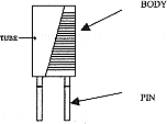
Through hole
This type has a very long history. We have used them for a long time before the surface mount technology has been developed.
Kinds of terminals
| (1.) Axial Leads: | (2.) Radio Leads: |
|---|---|
| CORE | RH, R2H, R6H, … |
| DWG | DWG |
 |
 |
The material of the coil:
- Core:
DRUM core, The most important material.
Sleeve core for shielded types. - POLYETHYLENE MAGNET WIRE (UEW)
The major is 2 EUW
Drum core inductors are so named as the conductor (round magnet wire) is wound directly onto the ferrite core which is shaped like a drum or spool. The wire is then connected to the core, a plastic base or metal lead frame to form the surface mount termination. Drum core inductors come in unshielded (high saturation current but potentially more EMI) and shielded constructions (lower saturation current but closed magnetic path for lower EMI). The shielded constructions use either a second ferrite core or a magnetic resin epoxy to create the magnetic shield.
1. Ferrite powder
- (1.) Mn-Zn, ferrite core
For large current, switching mode power supply. The working Freq.: Less than 1MHz.
TSL, TSS Types - (2.) Ni-Zn, ferrite core
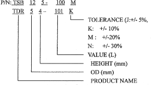
TSB, TDR
The performance is good when frequency is more than 1MHz
The notebook PC LCD inverter should use 4 pieces of TDR. Every kind of inverter of LCD panel back light should should use at least 1 piece of non shielded type (TDR)
The notebook PC converter should use 2 pieces of shielded types (TSB) and 2 pieces of non-shielded types (TDR).
2. Ceramic
- For high frequency, the IDC is low. It is used on RF. The SRF, Q should be very high at the frequency. (RF: Radio Frequency)
HCI – For example: mobile phone, blue tooth, and wireless instruments should use them as the filter or resonator.
3. Metal powder (Iron power, MPP, Amorphous)
- For very high current power inductors, its IDC could be very high. The inductance value would be very low. CPU & CPS. they would be used on the new generation CPU (P4) or the newer one.
A photocopier would use 2 to 4 pieces of this kind of inductors.
The mobile phone base station should use many pieces on the control board, add-on board.
| CORE MATERIAL | Q FACTOR | SRF | IDC | TOLERANCE | APPLICATION |
|---|---|---|---|---|---|
| CERAMIC | HIGH(1) | HIGH(1) | LOW(1) | TIGHT(1) | RF |
| FERRITE Ni-Zn | (2) | (2) | (2) | (2) | RF, POWER |
| FERRITE Mn-Zn | (3) | (3) | (3) | (3) | POWER |
| METAL | (4) | (4) | (4) | (4) | POWER (LOW L, HIGH CURRENT) |
| APPLICATION | Inductance (L) | Current ration (IDC) | IDC | Resonance Frequency (SRF) | Q Factor | DC Resistance (RDC) |
|---|---|---|---|---|---|---|
| HF circuits (RF), Resonance circuits | Low | Low | Very High | Very High | Low | |
| EMC | High | * | High | Low | Very Low | |
| Filter Circuits | High | High | High | Low | Very Low | |
| Switch-mode power supplies, DC-Dc converters | * | High | Medium | Low | Low |

- 1. Dimension of body, pitch (the terminal land pattern.). The size of the body is an important factor but isn’t the unique factor.</li?
- 2. The electrical character:(1). INDUCTANCE (L: uH): the elementary unit of inductance.(2) RDC: resistance of Direct current. (Ohms)It depends on the thickness and length of the wire.
The larger the thickness and the shorter the wire, the lower the resistance.If we need higher inductance we should wind more turns on the core so the thickness would be smaller and the wire would be longer, so the RDC is larger.Usually, the higher the inductance, the higher the DCR. - (3) IDC: RATED CURRENT
This is the working current. The function of the part should be good at this loading. - (4) Q Value:
Usually, the Q value is the larger the better. The RF engineer should be more concerned with the Q value because the application would be of a high frequency.The power engineer is less concerned with the Q value because the frequency is likely to be less than 1MHz, for example: the working frequency of the inverters or converters in a notebook PC might be around 300 to 600Hz.
The characters as below

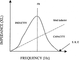
Fc <= 1/2 Fr or/and 1/10 SRF
Fc: Centre frequency
Fr: Frequency of resonant
SRF: Self-resonant frequency. (Series frequency)
-
- (5.) SRF Self-resonant frequency.
The RF engineer might be more concerned when it is for the frequency resonator because he needs high frequency.
The power engineer doesn’t care because the frequency is lo, maybe less than 1MHz. Usually, he would apply 300 to 600 kHz - (6.) Isat (A):
Saturation current. The inductor could work below this DC current. If the loading (A) is more than it the magnetic saturation would appear, the function would drop very fast. - (7.) Irms (A)
The temperature rising would be ^40°C when it loads some current. It might cause the copper loss or core loss. If the temperature becomes high, the efficiency could be lower and it is useless when the temperature reaches a certain point. - (8.)
If the value of inductance & IDC (the smaller RDC) is larger we need the larger core to meet the specification. The space of the PCB should have much limited so the dimension is a very important factor. - (9.)
Actually the IDC of our inductors is much larger than the specifications.
For example: TSB125-150M, The value of our catalogue is 3.3A but our ability is 5.5A.
It is designed for a notebook PC manufacturer. The engineer wants the component cheap and functionality good, it could be loaded with more current because the CPU is improved its speed then it needs more power to support it. We need the instrument to be lighter and smaller, so it allows smaller space for components.
- (5.) SRF Self-resonant frequency.