
A Guide to Choosing EMI Line Filters

EMI Line Filters | Am Transformers

EMI line filters are used in electronic devices, industrial equipment, household appliances and commercial equipment (such as vending machines), to reduce the effects of EMI on the performance of these devices.

Effects of EMI

Electromagnetic emission occurs due to a variation in the flow of electric current. This variation could be caused by natural occurrences such as fire, lightning, or other atmospheric elements.

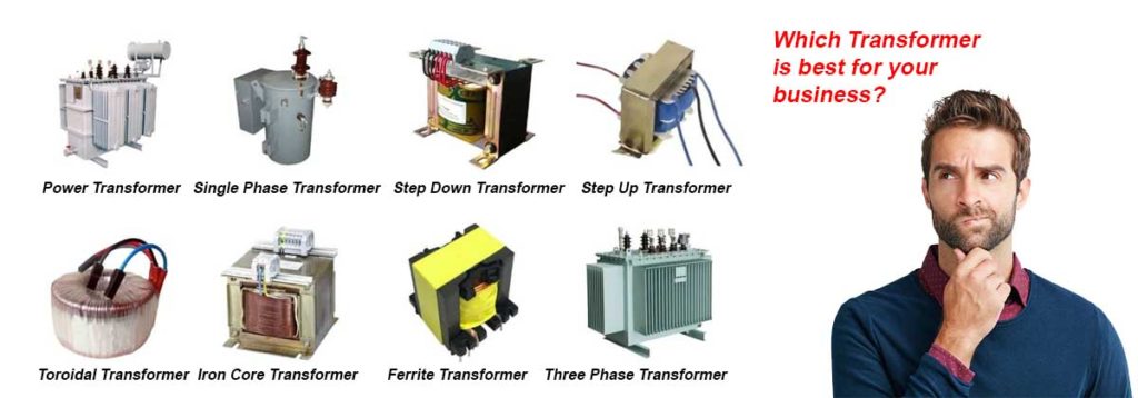
Artificial sources of electromagnetic emission include all those equipment and devices that are connected to electricity – equipment that runs on power or manages current flow. Industrial power equipment such as capacitors, inductors, transformers, resistors and semiconductors can be artificial sources of conducted EMI.

Interference occurs when the emission enters unintended electrical paths.

Conducted electromagnetic interference is one such form of EMI, which affects by inducing electrical noise. Electrical noise travels to the equipment connected to the power supply line experiencing EMI. This interference affects the equipment’s performance and renders it inadequate for its purported application.

Keeping EMI in check is also important for regulatory purposes. This is because EMI is capable of affecting not just the product connected to the affected supply line but the entire power network connected to the product. Your product must conform to regulatory standards of permissible EMI levels to be considered reliable and legitimate.

Benefits of EMI Line Filters

By reducing the EMI effects, EMI line filters help you comply with EMC (Electromagnetic Compliance) standards, and in keeping the performance of your equipment intact.

EMI line filters find application in two ways. They can be used to control electrical noise generated due to interference within a device, or they can be used to prevent electrical noise generated by other equipment in the vicinity from entering the protected device.

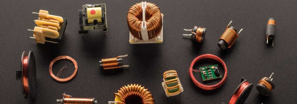
An EMI line filter features a collection of electronic components including capacitors and inductors that achieve the required objective, by forming an L-C circuit. A frequency far higher than that of a normal signal helps an EMI filter identify interference; the inductor part of the filter acts immediately by blocking or displacing the EMI signal.

The capacitor parts of the EMI filter work in tandem with the inductors to block high frequency signals from reaching vulnerable circuits. With all components of an EMI filter working to block any EMI, electrical noise neither enters nor leaves the device using the filter.

Key Parameters to Consider when Buying an EMI Filter

  • Operative Frequency – Operative frequency of the EMI filter is an important parameter. EMI filters that work for a wide range of frequencies are always better.
  • Operating Current – The type of current (AC or DC) to be used for the application in which the EMI filter is to be used.
  • Rated Voltage – This parameter refers to the maximum permissible line voltage that can be used on the EMI line filter.
  • Rated Current – This is the maximum permissible current that can be passed to the EMI filter.
  • Leakage Current – Measured in milliamperes (mA), leakage current is the amount of current that travels from the filter’s ground terminal when connected to an AC power source. EMI filter with a high leakage current value needs proper grounding or it can cause an electric shock.
  • Operating Temperature – The permissible range of ambient temperature at which the EMI filter can be operated.
  • Operating Humidity – The permissible range of ambient humidity at which the EMI filter can be operated.

Trust AM Transformers for Quality EMI Line Filters

At AM Transformers, we supply EMI line filters of custom-make as well as regular common mode type. We have been in the transformer industry for more than 20 years, and have been catering to businesses across the UK. We are reputed for our quality products and reliable customer support.

What are Inductors?

What Area Inductors | Am Transformers

Inductors are used to store electrical energy generated by current passing through the loop(s) of wire. The electrical energy is stored in the form of magnetic energy. Inductors find application in industrial components such as transformers and motors.

Inductors in Transformers

Coupled inductors are used to create inductance-based transformers. Coupled inductors have a common magnetic path. Therefore, a variation in one inductor affects the other. These transformers can be used for power distribution or voltage conversion.

Choosing an inductor with a high operating frequency is beneficial when purchasing inductance-based transformers. A magnetic field is created when variations occur in the current passing through the inductor coil. So, a higher frequency denotes faster variations in passing current, which delivers a high-performing transformer.

Inductors in Motors

Induction motors are extensively used in industrial settings. These motors work by converting the electrical energy in the inductors into mechanical energy. The magnetic force generated within the inductor coil is used for energy conversion.

A stater is the fixed component of an induction motor, which receives input current, and uses it to create a rotating magnetic field. This moving magnetic field comes into contact with another motor component – the rotor. The interaction generates current in the rotor, which in turn creates a magnetic field.

As the two magnetic fields (created by the stator and rotor) come into contact, torque is produced, which moves the rotor and accomplishes the task required of the motor.

This design of induction motors prevents the need for electrical contact between stator and rotor. This makes induction motors highly reliable for industrial settings. In addition, there are no components such as brushes in induction motors. This helps increase the life span of the motor.

Types of Inductors

Inductors can be classified into different types depending on the type of core they are wound around. The core is significant as it contributes to a stronger magnetic field. The magnetic force generated in an inductor with a solid core is greater than that created in an inductor that is simply a wound coil.

Some common types of inductors include:

Ceramic Core Inductors

Also referred to as air core inductors, ceramic core inductors are the most common and are used in applications that require high frequency input and a low inductance output.

The non-magnetic nature of ceramic ensures that the core does not contribute to any increase in permeability. Increase in permeability results in greater resistance to magnetic field formation, which affects inductor performance.

Another beneficial feature is ceramic’s minimal thermal co-efficient of expansion, which refers to the amount of expansion an object undergoes on heating. The low value of ceramic ensures that the inductor gives a steady output over a wide spectrum of operating temperatures.

Toroidal Inductors

Toroidal inductors have a core resembling a ring. The core is usually made of powdered iron or ferrite. These inductors are used in applications that require high inductance output at low frequencies. They are widely used in industrial controls, power supply equipment, power amplifiers, air conditioners, refrigerators and ballasts.

Power Inductors

Iron powder or ferrite core may be used for power inductors. These inductors are common in applications where voltage conversion needs to occur. Power inductors stabilise current flow in circuits that have variable voltage or current.

AM Transformers Fulfils All your inductor Needs

AM Transformers bring to you a range of inductors for all your industrial needs. We deliver custom windings as well. Our inductors comply with safety standards recognised globally as well as in the UK. With over 20 years of experience in supplying wound components to businesses across UK, we have become a trusted name in the transformer industry.

Choosing the Right Transformer for Your Business Needs

What Transformer Is Best For Your Business? | Am Transformers

The right transformer that meets specific business needs aids in business growth and transforms into an asset.

You will have to consider a several key factors, including the location of installation and performance requirements, when selecting a transformer for your business.
Choosing one without a assessing your requirements could result in waste of money and equipment that stunts your business’ daily output and long-term performance.
How to go about selecting the right transformer for your business? These guidelines could help.

Location
Will the transformer be installed within the facility, a remote location, or in the vicinity of seashore? Different locations demand different specifications for the transformer to perform efficiently.

For example, a transformer to be used outdoors should be able to handle different climatic conditions; such transformers usually come with a liquid used to safeguard the internal winding from outdoor wear and tear.

Similarly, a transformer to be used at a coastal location is susceptible to corrosion caused by the saline conditions. Transformers for such applications usually come with a corrosion-resistant coating.

Be sure to specify the location of installation so we can suggest a design suited to your choice of location.

Functions
Determine how you would want to use the transformer. For example, in an oil and gas facility, a transformer is inevitable for processes such as drilling, extraction, pumping and refining, and for handling other offshore processes.
A transformer may be required for complex heavy-duty applications, or for simple purposes such as powering a facility’s lighting system.

Specific Requirements
Do you want a space-optimised transformer for your application? Would you like to have your company logo included in the transformer design? Customisation is possible; simply specify such needs beforehand and we’ll take care of the rest.

Phasing
You can go for a single phase or 3 phase transformer, depending on your application. You need to specify the input and output voltage requirement, and the power rating in volt-ampere, for a single-phase transformer.
A three-phase transformer, common in industrial applications, for powering heavy-duty equipment, needs you to specify wiring configuration. Wiring configuration refers to the desired combination of the 3 windings of a three-phase transformer.

Voltage Requirements
Two voltage specifications – input and output – need to be defined. The input voltage refers to the voltage of the power supply source. Output voltage is the voltage required of a transformer to perform specified application.
While specifying output voltage, it is crucial to consider the highest load requirement of a transformer. This refers to the maximum voltage that a transformer would be required to supply as against the typical voltage supply for predictable applications on a daily basis.
Specifying the maximum load enables the transformer handle sudden unpredictable voltage requirements of an industrial setting without crumbling. This specification adds to a transformer’s durability as well.

Frequency Requirements
The frequency of your source of power supply determines the transformer’s input frequency. If you need a different output frequency, especially if you are using imported equipment, a frequency converter needs to be attached to the transformer’s output.

Safety Criteria
The type of industry, application of the transformer and the environment for which it is purported, often necessitate adherence to certain safety standards. It is crucial to check for such safety standard adherence of the transformer.

Reach AM Transformers for all your Business Applications
With over 20 years of experience in the business of transformers, AM Transformers is a trusted name that businesses reach out to, for their needs. We cater to a wide range of industries in the UK, and are known for our excellent technical and after-sale support.
Our experts are available to respond to inquiries. Place a call and avail the best products for your business.

AMT-Voltage Stabilizers

Voltage Stabilizers | AM Transformers

A Guide to Choosing Voltage Stabilisers Equipment in commercial settings such as manufacturing facilities and industries need voltage as specified by the manufacturer to perform well. A variation in voltage – low or high supply – can interrupt the functioning of equipment and can even cause damage.

Improper functioning or loss of critical equipment such as industrial refrigerators and computers can turn out to be expensive for your business, for they result in high maintenance costs, process crisis, and even business downturn.

Use of right stabilisers can effectively safeguard your equipment, and ultimately your business, from costly voltage problems.

How does a Voltage Stabiliser Function? This electrical device functions by supplying required voltage to your industrial equipment. It serves as a protective wall between the power supply system and your equipment. A voltage stabiliser monitors for, and recognises, any fluctuations in voltage from the power supply to your equipment.

If there is a fluctuation, the stabiliser employs an inbuilt mechanism (known as tap changer mechanism) to generate the required voltage to be supplied to the equipment connected to it (stabiliser). So how do you choose the right voltage stabiliser? As a buyer, you need to be aware of some factors that are important in choosing the right stabiliser for your equipment.

Do the following before shopping for a stabiliser: Specify Type of Power Supply Does the equipment that requires a stabiliser, run on a single phase power supply or three-phase supply? Specify the power supply system when choosing a stabiliser. This is important because voltage requirements vary for each power supply system. The actual supply voltage in the UK is 230 V for single phase supply, and 415 V for a three phase system. Once you define the power supply system, you get the corresponding voltage supply, based on which suitable stabilisers can be shortlisted.

Determine Total Power of Connected Equipment A voltage stabiliser can be connected to a single equipment, or it can feed multiple units. The power consumed by the equipment or the entire system of equipment, as applicable, must be determined. Equipment label or user manuals give power consumption details. Multiply the power value by the utility voltage (230 V for single phase; 415 V for three-phase), for each equipment. Sum individual power values in case multiple units are to be connected to the stabiliser.

Allow a margin of 20 to 25% to the total power value, to get voltage range for stabiliser. But, in general, go for stabilisers that offer support for a wide fluctuation range. Other Factors to Consider

  • Choose a stabiliser that facilitates wall-mounting. This is crucial to ensure safety of workers within the facility. Installing stabilisers in unsafe places, particularly where there is a risk of exposure to water, can result in electric shock. Wall-mountable stabilisers minimise such risks.
  • Go for stabilisers with time delay feature. This feature helps prevent possible damage to equipment that could result from a spike following a power failure. By delaying power to the equipment by a few minutes, the stabiliser restores balance and prevents damage.
  • Check if the stabiliser has overload protection capability. If stabilisers are loaded beyond their specified voltage capacity, they can break down, or worse, cause fire accidents. This protection feature prevents such occurrence by shutting down the stabiliser output completely in case of an overload.
  • Opt for stabilisers with a clear specified warranty period.

Trust AM Transformers for Quality Stabilisers AM Transformers has been in the business for over 20 years. Our stabilisers for single phase systems feature an input range of 216 – 278V while our three phase counterpart offers 374 – 481V input range. As a leading name in UK in voltage stabilisers, our experts are well-positioned to provide guidance and information regarding stabiliser requirements. Call us to discuss your needs. We promise you the best solution.

What Are 3 Phase Transformers?

What Is A 3 Phase Transformer | Am Transformers

Why Are They Used? Transmitting electricity at high current levels and low voltage is an expensive process. Transformers play a crucial role in electrical distribution systems. Utility companies distribute electricity to large areas using high voltages. When this electricity gets to the end point (your office or factory), it is converted to lower voltage with the help of transformers. Transformers are used to convert the voltage from the utility company to the voltage required to operate equipment in your premises.

What is Three Phase Power? Before we can understand 3 phase transformers, it’s essential to understand how the power companies generate electricity. The utility company has generators that produce electricity by rotating three windings or coils through a magnetic field. Each coil or winding is displaced at 120 degrees from each other. As these coils rotate through the magnetic field, they produce power, which is transmitted on three lines, which is nothing but 3-phase power.

Three phase transformers should have three windings or coils conjoined in the right sequence so as to match the incoming power, and eventually transform the high voltage produce by the utility company to the level of voltage required in the premises.

What Are 3 Phase Transformers? Transformers are essentially of two kinds, single phase and three phase. When we say single phase transformers, it means that you only need one conductor (consisting of one primary and one secondary winding) to transform the voltage received from the utility company. Three phase transformers consist of three conductors. That is, they contain three sets of primary and secondary windings.

It’s as if three single phase transformers share a joined core. Three phase transformers are much more economical when it comes to supplying large load. Be it the industrial sector, power generation or power distribution, three phase transformers are the preferred choice.

Advantages of 3 Phase Transformers

  • They use much less conductor material when compared for transmitting power to single phase transformers at the same voltage. For this reason, they cost much less to build when compared to a bank of single phase transformers.
  • Since they use less material, they are also much lighter and compact, and weigh less.
  • A three phase transformer makes use of three conductors to carry current, which results in a much more balanced load thereby providing a lot more power than single phase transformers.
  • Three phase transformers are highly reliable and operate smoothly and efficiently too.
  • If and when a fault occurs in any coil of a 3 phase transformer, the other two coils can be used to serve the 3 phase load. This is not possible in case of single phase transformers. This makes three phase transformers much more reliable.
  • Quick to assemble.
  • Easy to install and repair.
  • It’s possible to supply single phase power supply on a 3 phase transformer, but it’s not possible to supply three phase power from a single phase transformer.

How to Size Transformers? So how do you determine transformer size? Calculate voltage, power and current. You will require ‘turns ratio’, total load and primary voltage of the transformer to carry out this calculation. Secondary voltage is essentially primary voltage divided by ‘turns ratio’. Secondary current can be calculated by multiplying current ratio by the turn ratio. The power the transformer receives will be more than the power coming out of the transformer.

Choose AM Transformers AM Transformers are leading manufacturers of 3 phase transformers in UK. Manufactured to the highest standards, we bring to you high quality 3 phase transformers. We manufacturer 3 phase transformers of all sizes (up to 750 KVA) customised to your requirements. Customers trust us for our fast delivery, excellent prices and high quality products. Call us for custom designed transformers that meet your requirements.

Ferrite Beads

Ferrite Chokes And Cores | AM Transformers

Ferrite Beads

Ferrite is a black semi-magnetic crystalline structure that gives steel and cast iron their magnetic properties and it is a passive electric component that is used to filter and suppress the amount of high frequency electromagnetic interference (EMI) found in electronic circuits. Cylindrical in shape a ferrite bead consists of a mixture of iron oxide and other metals such as manganese, zinc, copper and nickel in various combinations. The material is formed into a hollow cylindrical core and cooked. The resulting core material is easily magnetized and demagnetized and is called a soft ferrite, however, ferrite material is mechanically rigid and brittle and can chip and break if mishandled, so they are encased in rubber or plastic material to protect them and keep the ferrite bead in place.

Also known as blocks, cores, rings, EMI filters, or chokes there are several different kinds of ferrite beads categorized by maximum DC resistance, case size / dimension, rated current, impedance, operating temperature range and packaging type, but the most common sizes for impedance are 120 Ω, 220 Ω, 600 Ω and 1kΩ.
Many ferrites are electrically non-conductive. In these types of ferrites eddy currents do not flow through the material which makes them suitable for use on radio frequencies in transformers, inductors, baluns and loopstick antennas.

How Do Ferrite Beads work?

A ferrite core or bead can be used in two separate ways to improve its ability to block unwanted electromagnetic interference.

In one instance, the ferrite concentrates the magnetic field which increases inductance and therefore reactance. This impedes or ‘filters out’ the noise. In the other instance, the ferrite can produce an additional loss in the form of resistance within the ferrite itself. The ferrite creates an inductor with a very low Q factor. This loss does create some heat within the ferrite, but it is negligible. When the electromagnetic levels are high enough to cause interference, or undesirable effects in sensitive circuits, the energy blocked is typically quite small.

Large ferrite beads are usually found on external cabling but various smaller ferrite beads are used internally in circuits. They are fixed onto conductors or around the pins of small circuit-board components, such as transistors, connectors and integrated circuits. Ferrite beads can be used for the removal of power line noises in cellular phones, PCs, TV tuners, audio players, DVDs, game machines, digital photo frames and several other electronic circuits.

Manufactured to international and UK safety standards, Am Transformers consider their ferrite bead production a speciality, so contact them today to discuss your requirements.